Erected in 1973, for the Electrification Section of the R&DD, the physical characteristics, spacings, dimensions, etc, of the part of the system were carefully worked out to produce an overall system whose behaviour was that of a system being used by trains running at twice the speed of the test vehicles ( See the layout plan below) . The facility was used to extend analysis of the performance and limitations of conventional catenary systems and current-collection equipment before moving on to the development of new designs of train-mounted equipment which enabled future electric vehicles to obtain efficient and reliable current collection. The various test programmes also included investigations into problems which might arise when two or more pantographs on a train were required to collect current at high speeds from a catenary whose equilibrium had been disturbed by the passage of the leading pantograph. It was thought that a theoretical mechanical limit existed to the maximum speed of current collection and during the track tests and investigations verification of this emerged. The OHLE was used for early pantograph development and for the testing of BR's Channel Tunnel proposals.
The installation
|
|
The original layout plan for the OHLE
Ron Broomfield collection |
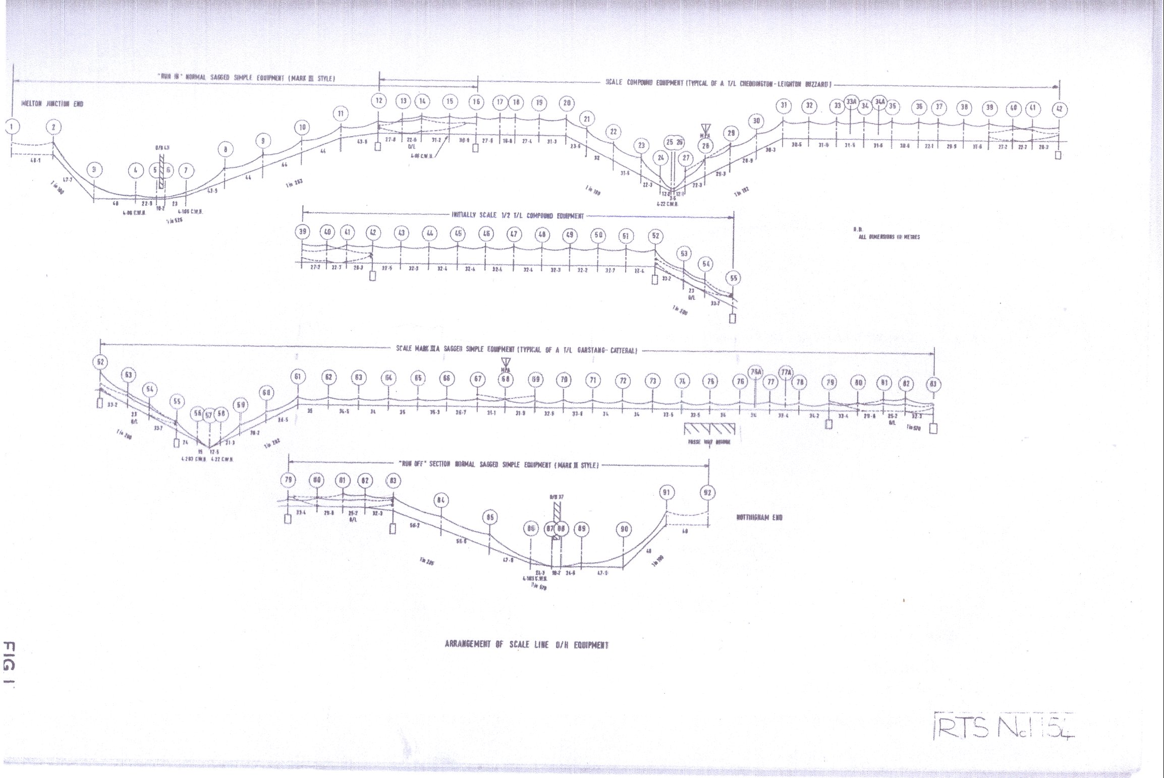
The overhead equipment comprised five different consecutive sections. From south to north they were :
- Run-in length (approximately ½ mile) of Mk IlIA type overhead equipment not dynamically scaled.
- Tension length (approximately ½ mile) of Mk I level compound equipment, dynamically scaled and modelled on a typical tension length at the Euston end of the London Midland Region main line (as it was in 1973).
- Half-tension length (approximately ½ mile) of level compound Mk I equipment dynamically scaled.
- Tension length (approximately ½ mile) of dynamically scaled sagged simple Mk IlIA equipment modelled on an actual section which was then located near Garstang in Lancashire.
- .Run-out length (approximately 1 mile) not dynamically scaled.
|
|
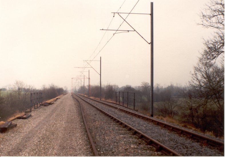
OHLE on Widmerpool
straight looking south Author |
Standard automatic power system (APC) track magnets were located at each end of the equipment to ensure that the beginning and end of the test length were indicated to the test vehicle and they could then raise or lower the pantograph as required. Instrumentation was fitted to the supports and overhead equipment at intervals so that parameters such as contact-wire uplift could be measured and recorded as the test train passed. Also included in the test length were two "artificial overbridges" where the support system and clearances had been adjusted to replicate bridge portions.
Over the years various designs of neutral section were also testing on the full scale tension lengths and these were instrumented and the pantograph filmed (using high speed cameras) as it traversed them.
It was never intended to energise the overhead equipment for traction purposes, although provision was made for the application of a low dc voltage for use in loss-of-contact measurements, the masts being electrically bonded to the rails.
Dynamic scaling and calibration
In order to achieve the effect of speed-doubling the basic construction parameters of the overhead line had to be adjusted by various factors. It was the value of these factors which determined the overall dynamic scaling ratio.
|
|
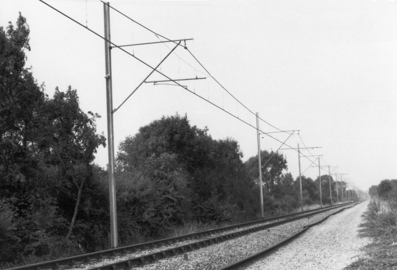
The scaled equipment on the Widmerpool
straight Author's collection |
A series of calibration runs were made initially using a conventional pantograph to verify scaling factors. The measurements obtained were compared with those recorded on test runs at twice the speed under full-scale catenary and good correlation was obtained.
Test vehicles
Instrumented pantographs mounted on the roofs of one or both of the two test vehicles were used to measure a variety of parameters in test runs. These included: upper joint trajectory, secondary suspension movement, force applied under the pantograph head, head acceleration, loss of contact. Signals from the transducers fitted to the pantograph were displayed on an ultra-violet recorder for immediate reference and also recorded on a twelve-channel analogue tape recorder for subsequent digitisation and computer analysis at the Railway Technical Centre. On the test runs, datum points were obtained and recorded using photo-electric cells to detect the passage of structures; contact force was determined by using a summing circuit to combine the measurements of head acceleration and force applied under the pantograph head. Visual observations of the roof-mounted equipment and the overhead line were made through an observation dome.