Operation of the Line

Prior to its recent upgrade, when the line was operated by BR, it was a single-ended line which connected with Network Rail's infrastructure at Melton Mowbray .

From the Melton end, the line today passes through pleasant countryside past the villages of Asfordby, Saxelbye, Old Dalby, Plumtree, Keyworth and Tollerton to Edwalton, just south of West Bridgford on the southern outskirts of Nottingham, where it terminates. Although it was universally known as 'Old Dalby' the official name for the test track was the 'Asfordby Junction Ground Frame (GF) to Edwalton' Line. After Alstom had upgraded the line was supposed to known as the Alstom Midlands Test Centre (AMTC), but most people still referred to it as the 'Old Dalby test track'.

Old Dalby Instructions 1974

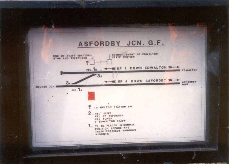
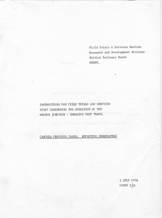
This is the front cover of the R&DD Operational Instructions for the line dating from 1974. It was run by the Field Trials & Services section where the author worked for a number of years.

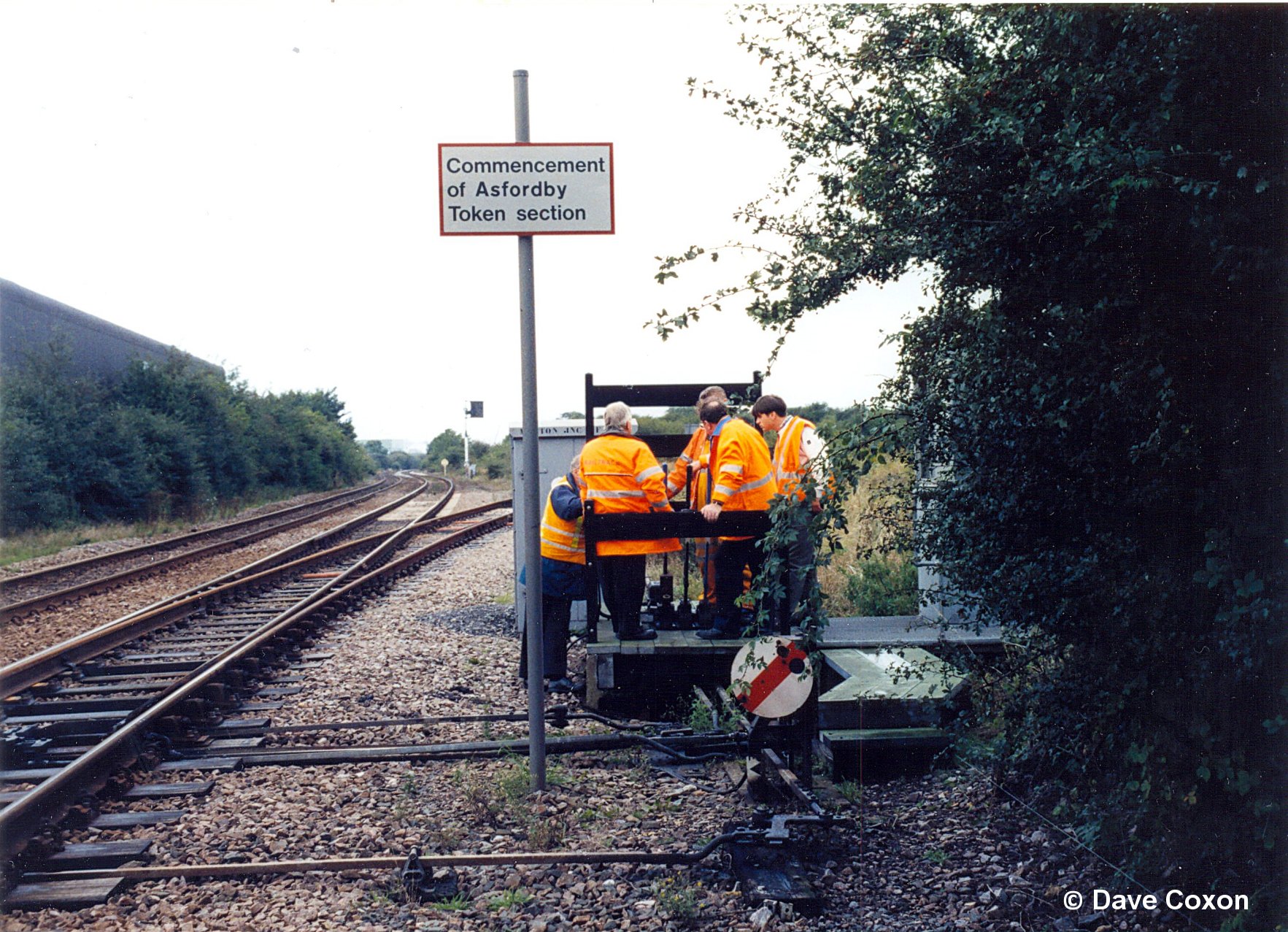
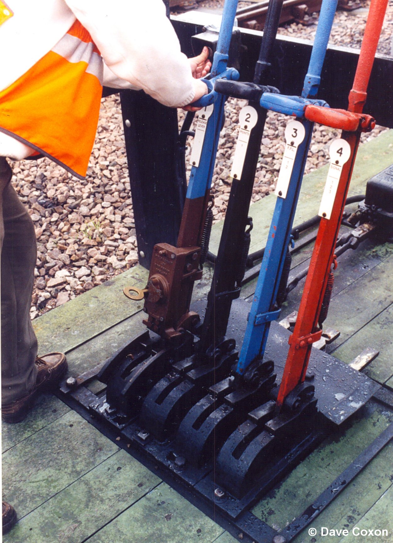
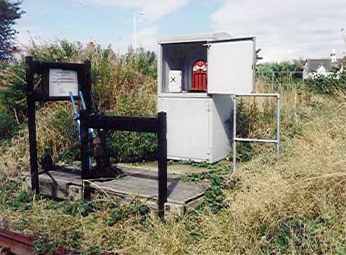
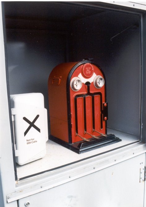
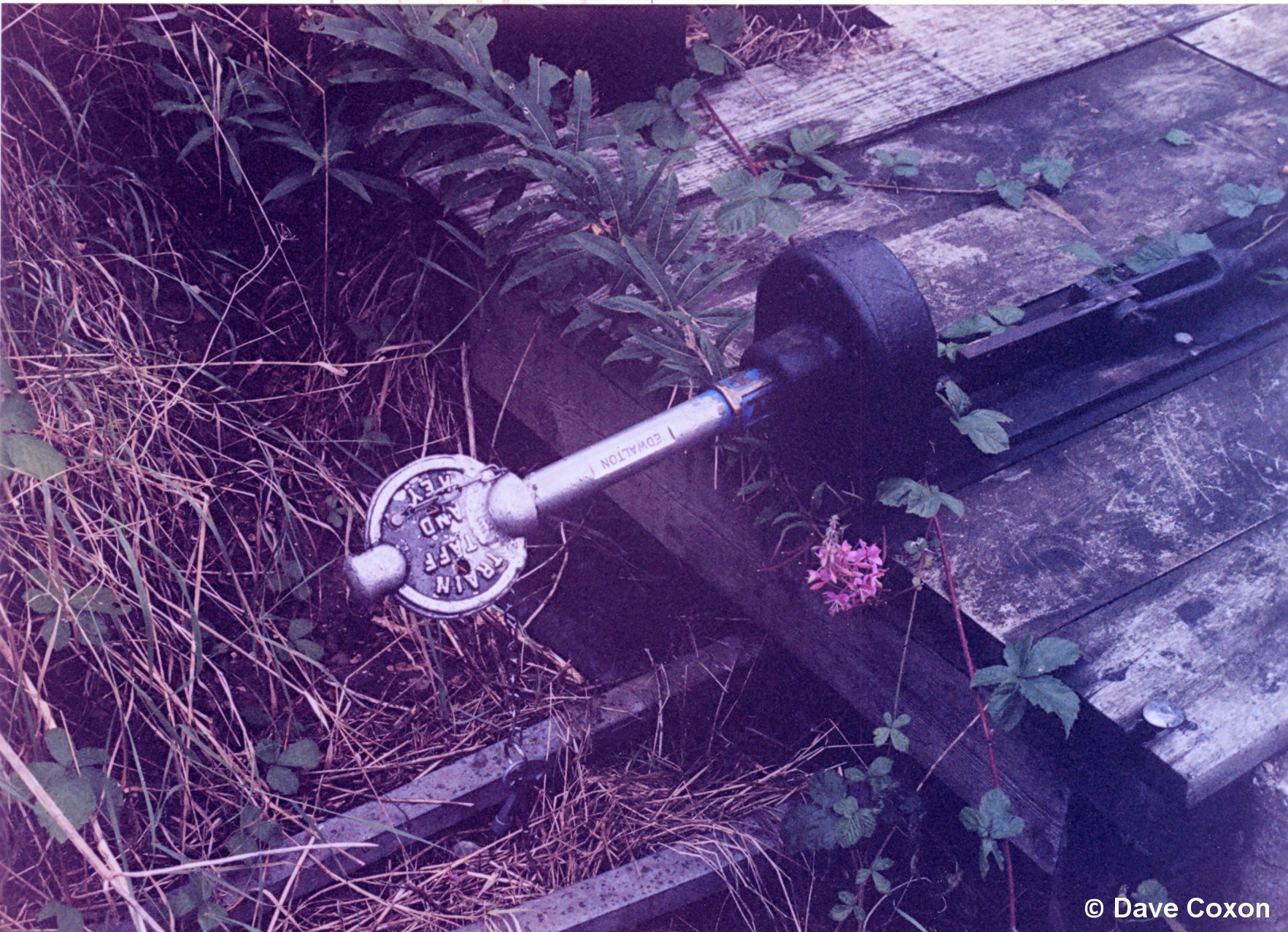
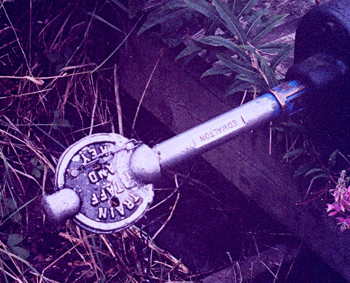
Rail access is via Melton Junction through a token-controlled manually-operated ground frame released from Melton Station Signal Box, which is still (2007) in an area of mechanical signalling. Trains arrive at Melton Mowbray, usually from the west and stop by the station signal box. The train crew or the 'Officer In Charge of the Train' (OICT) then collects and signs for the 'Edwalton Train Staff and Annetts Key' from the signal box. The train is then signalled to reverse back along the Up line in the 'wrong direction' towards Melton Junction GF, which is situated near the 106¼ MP. The mileage is measured from London St. Pancras Station via Kettering, Glendon Junction, Corby, Harringworth Viaduct, Manton, Oakham and Melton Mowbray.

Melton Jcn GF

Melton Jcn. Ground Frame: the access line to the test track and the former Alstom Control Centre at Asfordby leaves the Leicester to Peterborough Up line at this point. The sign refers to the staff section to the former mine. Note the Ground Signal showing a 'proceed' aspect and the points lying towards Asfordby.

Author

This GF controls access from the Network Rail main line from Leicester to Peterborough onto the Network Rail single-track line, which leads to the new HQ and depot and from which access is gained to the test track. The Melton Jcn GF is operated by a small Tyer's key token, which is obtained from the Token Machine after being electrically released by the signalman at Melton Station Box. The OICT obtains the key token, which is then used to mechanically unlock the ground frame. Once the GF is operated the train may then move onto the single line and the GF is returned to 'normal' behind it and re-locked by removing the key token. All these actions are monitored by the signalman in Melton Station box, such that he is aware when the main line is back to normal. The key token is retained by the OICT for use at the Asfordby Junction GF.
Melton Jcn GF closer The Melton Junction GF in close-up. The small Tyer's key token can be seen protruding from the base of the left hand lever. Once the signalman has released the frame electrically the key token can be used to unlock the frame. The photograph shows the button being pressed by the operator's left hand. 

Author

With the appropriate token in the driver's possession, giving him authority to be on the line, the train travels along the half mile long single line to Asfordby Jcn. GF, which is just south of overbridge 61, near milepost 106¾.

Asfordby Junction GF showing the red Tyer's Token Machine in the cabinet alongside which is the telephone (in the box with the cross). This connects directly to Melton Station Signal Box, as the signalman has to release the Token Machine in order to receive the Tyer's token from Melton Jn GF, once the train is on the test track.. This GF has two levers, one for the facing points lock and the other for the crossover. The large Annetts lock can be seen on the LHS at the base of the left hand timber post.

Author

Asfordby Jcn Token Machine

Token machine

A closer view of the Tyer's Token machine. The tokens can be seen protruding from the bottom of each slot. To remove one it is raised to the top, and when the signaller releases the lock it is twisted and removed. The dials indicated when the lock is released.

Author

Asfordby GF diagram

The track diagram adjacent to Asfordby GF shows the layout and denotes the lines.

The test track is shown as the 'Up & Down Edwalton' line and the line to the former mine as the 'Up & Down Asfordby'

Author

This GF allows access to the test track over a crossover, the line to the originally defunct site of the mine carried on to its own token machine at the colliery site. Asfordby Jcn. GF requires the use of both the key token and the Annetts key to unlock it and to allow access to the test track. Once the GF is unlocked the crossover is then reversed to allow the train on to the test track, then it is returned to normal and the Tyer's key token, which was acquired from Melton GF is left in this machine. The Edwalton Train Staff and Annetts Key is also removed from the GF and is carried on the train as the authority to be on the test track. It is thought that this method is still in place although the track can also be accessed from the Asfordby complex.
The 'Train Staff & Annetts Key' in place to unlock the Asfordby Jcn. Ground Frame. Note the point rodding.

Author

Staff and Annetts key
Once 'inside' the train is locked into the test line and no other trains can gain access unless they are in possession of the 'Train Staff & Annetts Key' . Under BR the test track had no signals although it did have a number of AWS (permanent) magnets spaced at approx.1 km intervals throughout its length.
View towards Asfordby tunnel The view north from Asfordby Ground frame. The test track is on the left, the 'Commencement of Staff Section' sign denotes the beginning of the line. The Network Rail line to the defunct mine (now the new depot) is on the right. The southern portal of Asfordby Tunnel lies through the overbridge.

Author

 As the line was infrequently used (compared to the running railway), it was customary to carry out a 'proving run' before testing commenced. The train would traverse the whole of the line at a reasonable speed to ensure that it was free of obstructions etc before returning to Old Dalby, where the Control Centre, workshop and kettle were situated.

At Old Dalby there is a further ground frame which allows access from the line into the sidings and workshop and this too is unlocked by use of the 'Train Staff and Annetts key'. If required a train could be locked inside the sidings and the train staff returned by road to Melton Signal Box to allow further trains onto the test track.

Only one train was allowed to run on the main test track at any time.

The Northern part of the test track - NB This 1999 map still shows the line running into Nottingham!

Map of northern part

The line terminates just north of the A606 / A52 junction which is just above the 'n' in Clifton on the above map. The line skirts Keyworth and then passes through the old Widmerpool Station, which is near the A606/A46 junction just below the 'y' in Keyworth.

 The Southern part of the test track

The Old Dalby control centre was situated within the triangle bounded by the three roads to the north west of Melton Mowbray on the above map.

The new Asfordby Complex is just to the north of Melton Mowbray.

Map of southern part

The control centre for the track was at Old Dalby (111¼ MP) and consisted of a single storey wooden building block housing a control room, messing facilities, toilet and conference room. There was also a small rail-served workshop with a 5 ton overhead crane and an inspection pit. The workshop and the control centre were surrounded by a 4 m high security fence. Test trains could be stabled within the compound if required. These facilities still exist but the office accommodation has been added to and the workshop has been extended. There is now a northern outlet onto the new 'Up', line which is used for the Train Control System testing. The class 309 EMU's used in connection with this are stabled at Old Dalby. All other functions are now conducted from the new complex at Asfordby.

Since the early1970's the line has been equipped with a 2 mile length of overhead line equipment (OHLE) running from Folly Hall curve near 113¼ MP to just north of Widmerpool Station at approximately 115½ MP. This OHLE was not powered and several tension lengths were erected as 'half-scale' having spans of 35m instead of 70m thereby allowing trains to simulate running at twice the actual track speed. It also had several different styles of overhead equipment on the other tension lengths but up until the upgrade in mid-2000 had not been used for testing for a number of years and was in a poor state of repair. The line today is electrified from Asfordby to a point just south of the former Plumtree Station.

OHLE details

This is an article from the July 1973 Modern Railways magazine describing the system

There is a straight run of over 3 miles from 113¾ MP to 117 MP, which is still the preferred location for high speed running.

The line through Stanton Tunnel was the only part of the original test track to retain double track, which extended to a point approx. 500m south of the southern portal. Access was via a GF just outside the northern portal. This had been used to stable other vehicles for the purposes of conducting aerodynamic passing tests etc. particularly with APT-E. Today double track extends from Old Dalby to beyond Stanton Tunnel, having a length of approx 6½ miles in total.

Gradient Profile

Gradient Profile and schematic plan of the test track in BR days

Back to Main Index