Alstom Transport Limited (ATL) was commissioned
to build a test track at Old Dalby, Leicestershire by developing an
existing, unused, non-electrified railway line. The primary use of the
track was to carry out testing of the new tilting trains to be run on
the West Coast Main Line.
The track was to be electrified at 25 kV, 50 Hz by feeding it from the
National Grid through East Midlands Electricity (EME) at 132 kV via a 10
MVA, 132 kV/25 kV single-phase transformer close to the existing RJB
Mining Ashfordby main intake substation end of the tests track. The new
substation was to be constructed on RJB land adjacent to its 132 kV/11
kV main intake substation.
The existing substation has two separate 132 kV/11 kV distribution
transformer feeders. These feeds are tapped from the primary side of the
132 kV/11 kV transformers to feed two 132 kV/25 kV transformers in the
new Old Dalby test track substation. Each of the two 132 kV/25 kV
transformers is connected to a different 132 kV feeder line. They are
interlocked so that only one supplies the test track at any given time
whilst the other remains on standby. Since the substation will be 1.1 km
(0.66 mile) away from the test track, there is a 25 kV wooden pole
overhead line that conveys the supply to the test track via a trackside
feeder station.
Turner Townsend Project Management was already involved in the on-site
buildings construction and PB was requested to assist them as technical
advisors in respect to railway mechanical and electrical issues.
The Objective
The challenge was to achieve power available and energised to the test
track in less than six months. Hence, there was a need to stage the
works because the complete and final design implementation would not be
possible before the desired end date. If the energisation date was not
met, then embarrassment together with possible financial penalties might
have occurred in accordance with the agreed contract for the supply of
the class 390 trains.
The main requirement, therefore, was a suitably rated power supply of
sufficient provision, with standby or backup facilities, to run a number
of Class 390 trains up and down a test track of 17.5-km (10.5-mile)
length. The same supply would also be used to stable and manoeuvre
trains in the light maintenance depot. A latter requirement added
thereafter was verification of electromagnetic compatibility (EMC) and
electromagnetic immunity (EMI) issues between the traction power supply
and signalling equipment that would now be housed in the light
maintenance depot. Primarily it was not envisaged to introduce the
catenary’s 25 kV power supply into the building and, hence, the vicinity
of the signalling control centre.
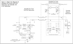
Figure 1: Single Line Diagram of Asfordby Test Track 132/25 kV
Substation and Asfordby 132/11 kV Substation |
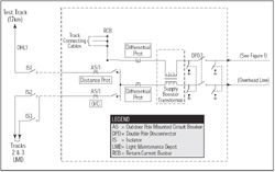
Figure 2: Asfordby Test Track Feeder Station |
Table 1: Interface Responsibilities
 |
Design Concept
By the time we were invited to participate as advisors and design
checkers, the contractor, Alstom Transmission and Distribution Ltd.
(AT&D) had already provided the preliminary draft design diagram and
equipment support information to the client, ATL, as a proposal. The
traction power transformers were already on order. That meant the
overall design needed to be actually ongoing and developed during the
tight program schedule.
For this unorthodox approach, a co-operative and co-ordinated team
effort would be required from all partners—from the simulation and
modelling specialists through to the various contractors operating on
site. Our team managed the co-ordination of the design development,
producing interface responsibilities and chairing technical meetings
with the parties involved to that end.
The single line diagram in Figure 1 shows how the 25 kV power supply is
derived from the 132 kV tower at the RJB intake substation and delivered
via a 1.1-km (0.66-mile) overhead transmission line to the trackside
feeder station (Figure 2). The interface matrix provided in Table 1 on
the following page gives an idea of the companies involved and their
respective responsibilities, as co-ordinated by PB.
Development and Stages of the Work
Time was of the essence in terms of providing a supply to the test track
in a few months, so it was necessary to work on the basis of
implementing various installation stages in line with equipment
availability and EME/RJB permitted outages. Stage 1 had to involve a
direct bus connection to the primary side of RJB’s 132 kV/25 kV
distribution transformer that temporarily relied on protection through
an existing fault thrower backed up by the EME network. Other stages
were planned to connect the standby traction power transformer and its
associated equipment, as well as the developments described below.
132 kV Metering. It became apparent during
design/co-ordination meetings that commercial metering of the supplies
could not take effect at 25 kV, as this would involve a second user. RJB
owned the site and already had an agreement with EME, so only one or
sole user would be legally acceptable. Metering would have to take place
at 132 kV, meaning additional switchgear and protection would be
necessary, as shown in Figure 1. This development placed added pressure
on the design and installation phases and constituted a second
installation stage. Furthermore, check metering was also included to
assist in the monitoring of consumption relative to the test track.
Problems Due to Negative Phase Sequence. Studies and
measurements by EME showed existing high, out-of-phase, negative phase
sequence phenomena on their network. The introduction of the traction
loads from the test site would exceed the recommended requirements of
Engineering Recommendation (ER) P24 when added to the existing
background levels. The fault level at the Asfordby main intake
substation was significantly low enough to maintain a negative phase
sequence that was above the requirements.
One option was to install a new 132 kV grid site in the vicinity to
increase the fault level. This solution would take at least five years
in terms of planning, design and installation, however, so did not
provide a remedy in the short term. Phase balancers, although less
expensive in relation to a new grid site but known for their
effectiveness, were considered as an alternative. There was sufficient
space adjacent to the RJB mining 132 kV/11 kV substation site.
Therefore, another future but final installation stage would need
consideration.
Introduction of Phase Balancing. The design principle
and objective of a phase balancing system is to eliminate completely the
negative phase sequence currents by adding one or more other
single-phase loads. The most orthodox or obvious way of achieving this
and correcting the unbalance that results from a single-phase load is to
equalise the three phases by adding appropriate single-phase loads into
the other two phases. This is not easy to achieve practically,
especially for a variable or dynamic load. The real and reactive power
of the traction load must be monitored and then the appropriate control
signals generated to the thyristor controlled reactors. This will then
provide the required value of reactive power output in each phase.
Independent control of each phase of the balancer is needed to obtain
the necessary correction of the single-phase load.
Phase balancers generally take about 18 months to design and manufacture
from when the various technical parameters are known. The size and
layout of the equipment is quite formidable. Fortunately, there was
knowledge of an existing balancer that could be modified and adapted,
thereby having the advantage of reducing some of the lead-time.
Connections for the phase balancer are shown in Figure 1.
Earthing and EMC Issues Within the Area of the Light Maintenance
Depot. The 25 kV overhead line catenary power supply was
originally going to be wired up to a distance remote from the light
maintenance depot. The building’s internal services would be in
accordance with and signed off as compliant with the IEE regulations.
Later requirements dictated that the 25 kV traction power supply would
be brought into the building, however. The signalling and
telecommunications engineers then raised concern over this change of
requirement because their equipment, which was originally designed to be
housed in rooms within the light maintenance depot, might now be
subjected to potential traction faults in terms of touch voltages and
EMI/EMC issues.
Power Up and Tests. A test procedure document and test
plan was conceived by PB in advance of the power-on date and made
available to the client and the relevant disciplines. Stage one of the
power supply design was completed on time, prior to delivery of the
first vehicle for ceremonial use. Power was switched on in a controlled
manner late at night via an approved switching procedure involving PB,
EME Border (overhead catenary installation specialists) and AT&D, the
main mechanical and electrical power supply equipment designer and
installer.
Load Tests. Although one of the Class 390 vehicles was
delivered and thus perceived available for initial load tests,
sufficient steady load in terms of continuous current could not be
successfully drawn. A contributory factor was the not-fully-commissioned
lighting, air conditioning and heating that could have provided the
appropriate minimum “pick up” values and thus prove the protection
relays. This problem was rectified and verified at a later date along
with other measurements to satisfy the EME and ATL.

Figure 3: Principle of Current Distribution - No Booster
Transformers |
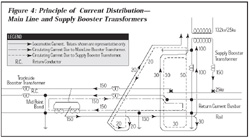
Figure 4: Principle of Current Distribution - Main Line and
Supply Booster Transformers |
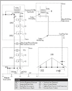
Figure 5: Distribution of Percentage Traction Current Prior to
Insertion of Mains Booster Transformer |
Mains Supply Booster Transformer.
Initial current measurements revealed that a larger than normal
percentage of return current was travelling back to the substation via
11 kV cable sheath earths in the vicinity of the light maintenance depot
and RJB’s coal preparation plants. Earth return currents may share up to
15 percent to 20 percent of the total current delivered by the
substation site. Although load currents were low due to the use of a
non-fully-commissioned train’s auxiliaries static load, a 54 percent
share of the return current via earth was ascertained by current
measurement transformers, with only 46 percent flowing back in the
return conductor path (Figure 3). A means to overcome this phenomenon
had to be developed and applied in the medium term before the loads
became significant.
A supply booster transformer has the capability of encouraging the
return currents to flow in the return current system (Figures 4 and 5).
Although other power supply isolation methods were considered, this
option proved to be more economic and less disruptive. A supply booster
transformer was thus acquired and installed inside the trackside feeder
station immediately after the completion of stage one. This application
was successful in performing the desired effect and encouraged the
currents to flow through the orthodox return current conductor system
route.
Technology Impact
Strictly speaking, the technology used in the design applications does
not have an impact, as such, on PB because it is generally included
within the human resource and expertise of its personnel. One could
argue, however, that there is an impact in the sense that working with
this technology broadens or bolsters our experience base. The impact of
the technology to the project is, for example, in the introduction of a
mains booster transformer, paramount in finalising a successful design
whilst being cognisant of safety and economics. Moreover, such elements
of this technological know-how contributed “added value” to the project.
There were no “new” technical developments to be perceived as such, but
the introduction of the mains supply booster transformer and the phase
balancer, the resolution of the earthing issues and how they came about
were innovative on the part of our key team members. Particularly unique
was the fact that all this phenomena occurred on the same project and
under very tight time scales for resolving such issues.
The Future
At the time of writing, there are still the remaining design stages yet
to take effect. Stage 2 involves the installation of the second traction
transformer, 2-phase 132 kV circuit breakers and 3-phase 132 kV circuit
breakers with their metering facilities. A final stage will include the
installation of the phase balancer. These remaining stages are currently
ongoing and will run on until the end of the year, thereafter to provide
what is perceived to be a reliable and secure power supply, not only for
the testing of tilting trains but also for the variety of other vehicles
that come off the production line. Moreover, a British test site will be
available to put them through their paces.
End Note
Hopefully, this article is helpful and interesting for those working not
only in the area of traction power supply, but also for those involved
in the realms of technical project/engineering management. Our team was
interfacing with a variety of contractors and designers who all worked
extremely hard
to satisfy the client’s requirements. |


