One can imagine that wheelsets such as this (machined from a solid wheel) can be very costly although R&DD made a small production line and the author spent a number of months attaching strain-gauges to these LMW's.
BR Official
| Load
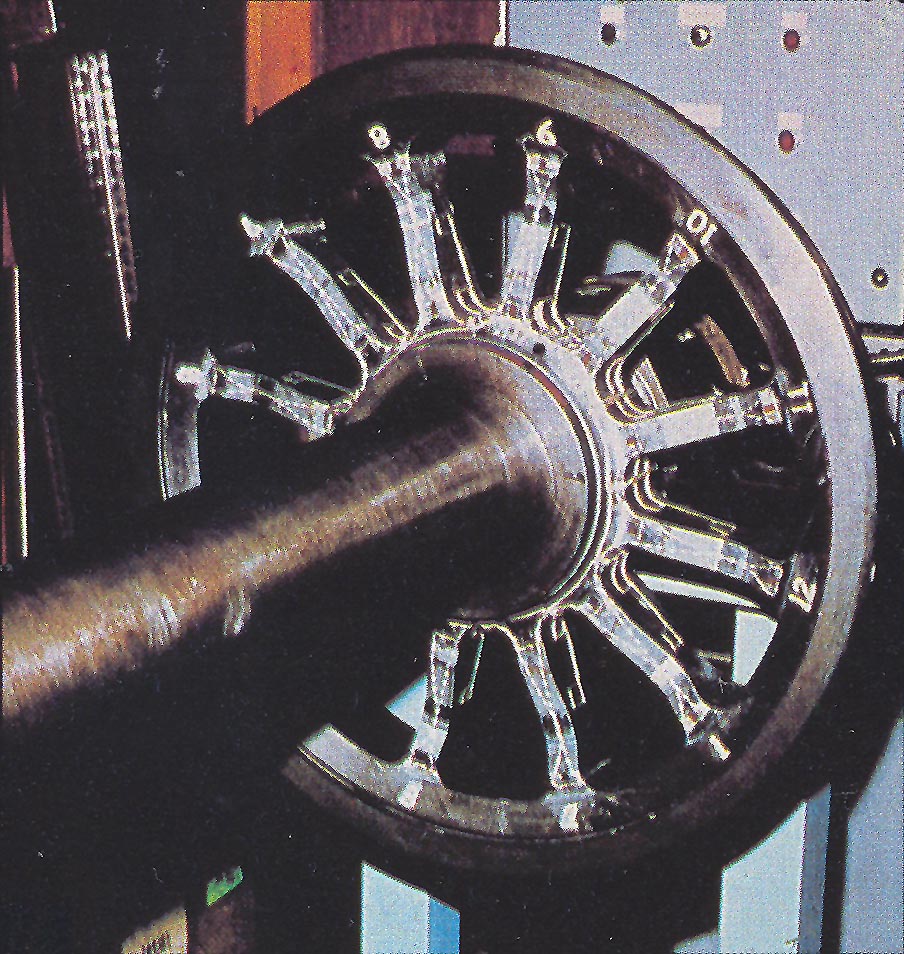
measuring wheel testing Following internal changes, in 1976 I found myself working for the Dynamics Group looking at wheel/rail interface problems. This involved the deployment of one or more load measuring wheelsets (LMW). The wheel set was very expensive as each spoked wheel was machined from a solid blank wheel and strain gauges were then attached to the spokes at pre-determined positions to measure vertical, lateral and longitudinal loads. The output signals from the wheel passed through a set of slip rings mounted on each end of the axle. The signals from the vertical load circuit needed to be manipulated including part-inversion to give a steady output signal related to the wheel load. The other two aspects did not need such doctoring. |
Click on the picture for a bigger image - all photos are the author's unless otherwise credited
|
|
This is a
Freightliner LMW during its construction, pictured on the calibration rig in
the R&DD workshop. Note the wiring for the gauges (vertical, lateral and
longitudinal) and the slip ring assembly glimpsed through the spokes. One can imagine that wheelsets such as this (machined from a solid wheel) can be very costly although R&DD made a small production line and the author spent a number of months attaching strain-gauges to these LMW's. BR Official |
|
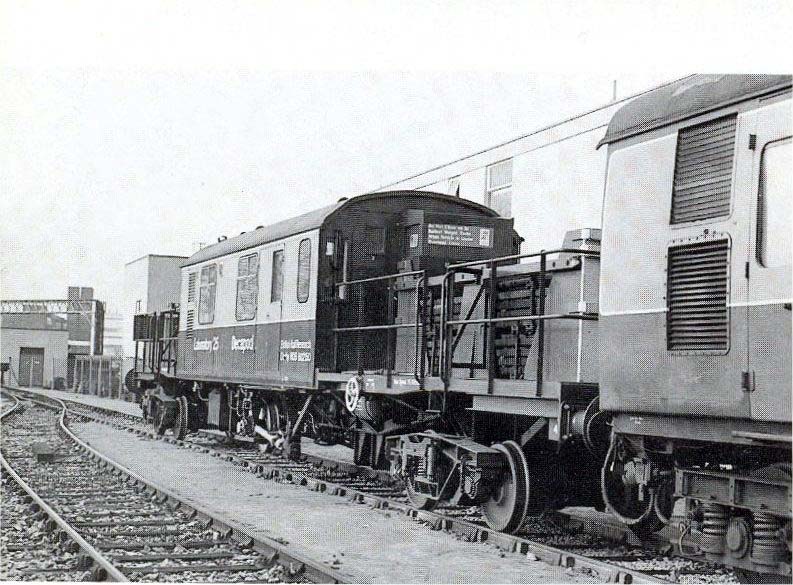
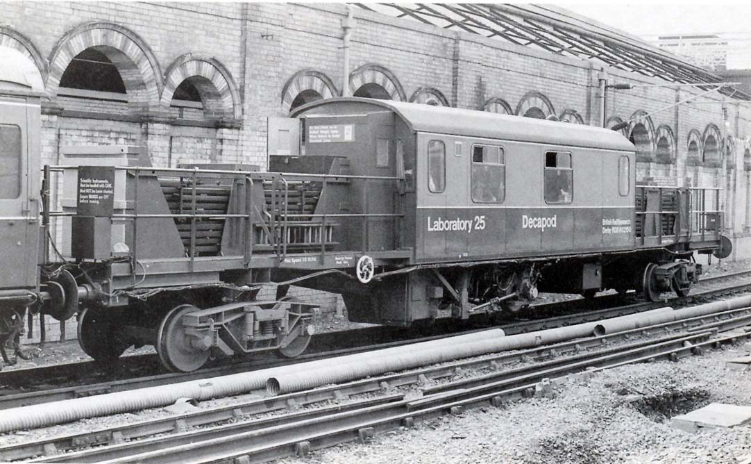
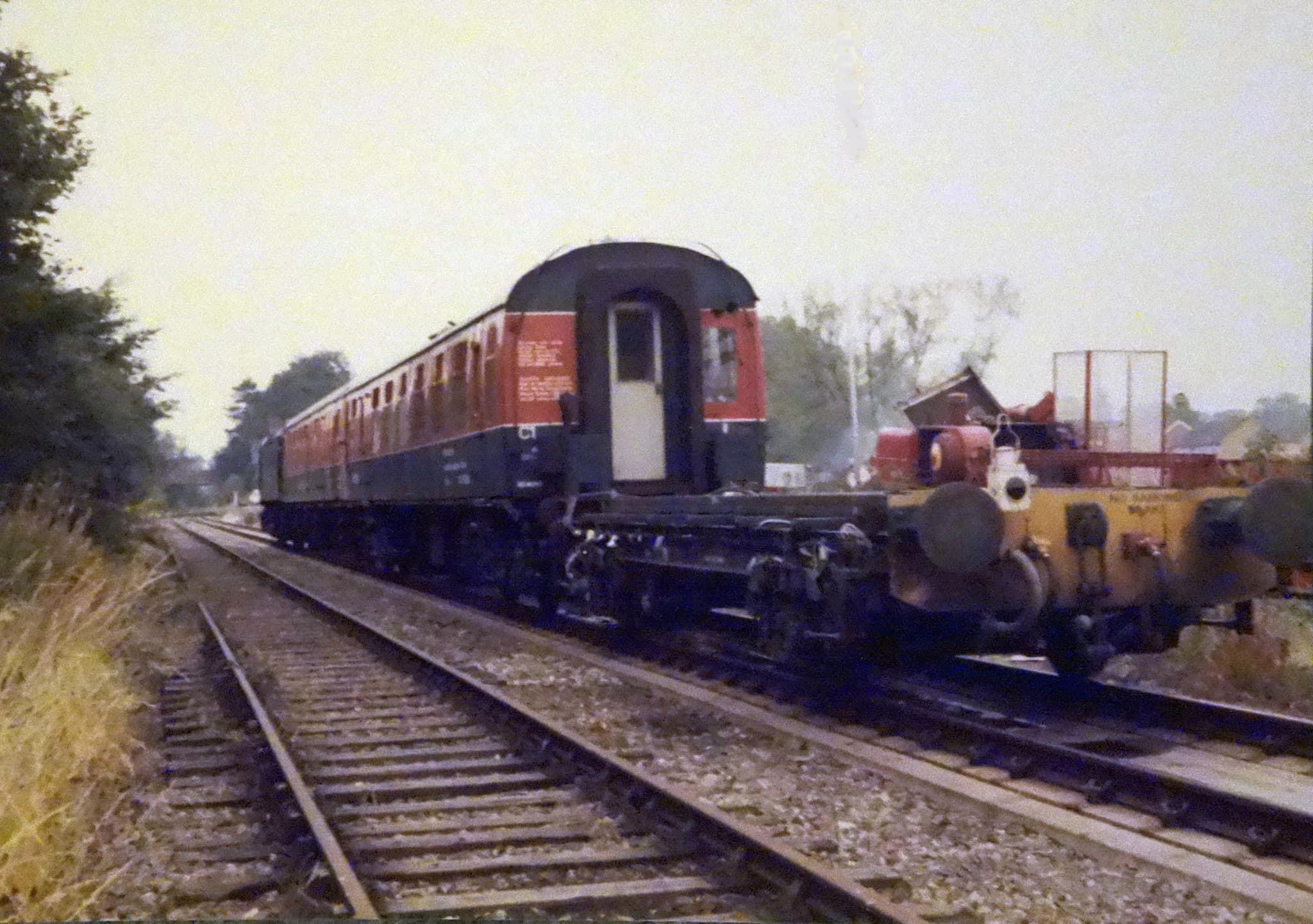
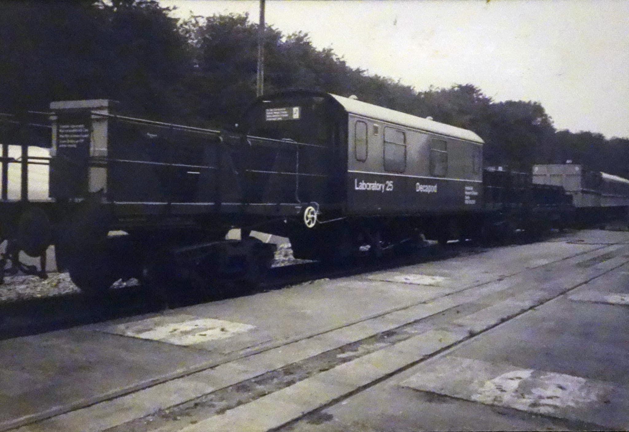
In the Research Division of BR in the 1970's there were several projects which utilised load-measuring wheelsets (LMW). Several of these specially-designed spoked wheelsets were manufactured from solid blanks and were delivered to the RTC where they were strain-gauged by the author and colleagues. A special rig was set up within the R&DD main Test Hall workshop where this work was undertaken and where the wheelsets were calibrated. This was separated from the shop by sackcloth-covered wooden screens and was hence known as the 'Hessian Hut'. One test series which I was involved with was the curving tests undertaken with HSFV1 using two of the wheelsets on the four wheeled wagon. Later in the project, a special vehicle was built for the purpose of detailed investigation into lateral track forces, curving and rail corrugations. This vehicle was a converted Freightliner flat which was fitted with low track force bogies in place of the normal Gloucester 3-piece and had its chassis raised. A retractable LMW was fitted between the existing bogies. Onto the centre of the vehicle was built the accommodation for the crew and instrumentation and the outer ends were left open and used for loading purposes - note on the photos the rail packs which were also used on HSFV1. Later known as Lab 25, (RDB602150) it now had ten wheels and consequently, in true R&D tradition, was christened 'Decapod'. Although the author was involved with a number of tests with the vehicle, I left the Project before it was completed. |
Click on the picture for a bigger image
|
|
RDB602150 Decapod in the
loop at the RTC Colin Marsden |
|
|
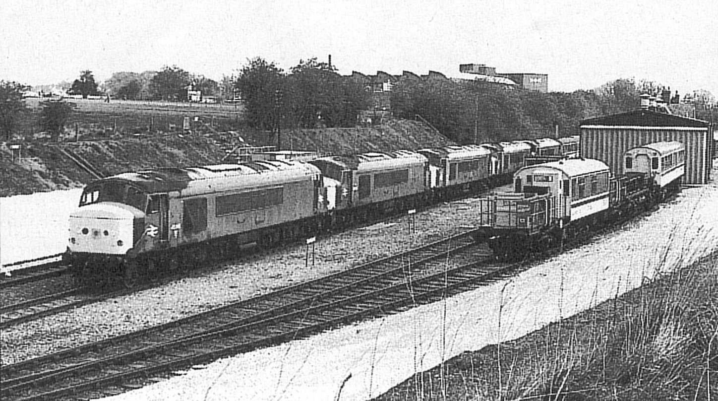
Decapod on a test
train pictured in Crewe station sometime in the late 1970's John Tuffs |
|
|
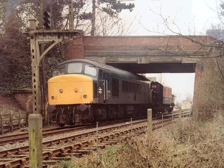
A class 45 with Decapod at
Etwall in 1985 Gerald Anthony |
|
|
Out on the Mickleover test track
with Lab One
Bill Poole |
|
|
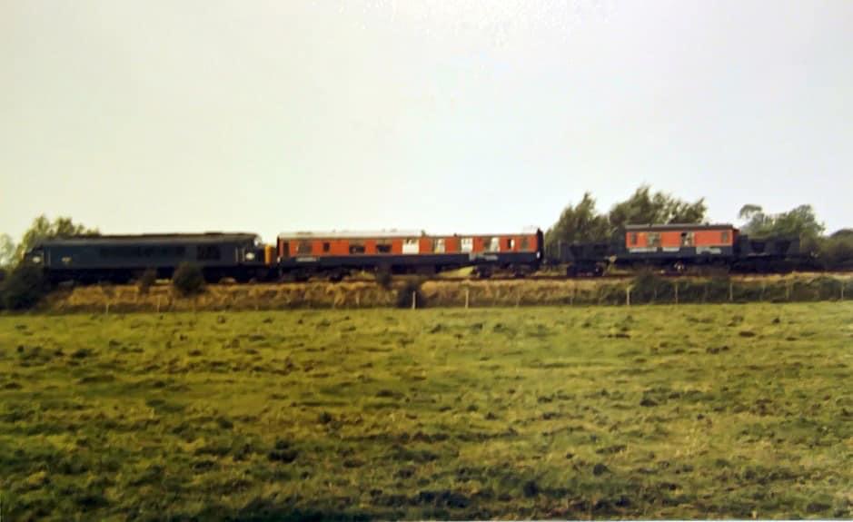
Here it is in the company of
HSFV1 near Etwall ..........................
Bill Poole |
|
|
..............and again at Mickleover in 1990 P Graves |
|
|
Lab 25 at Mickleover
Bill Poole |
![]()