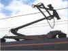
Aerodynamic tuning was achieved in the following way.
The pantograph was raised in the normal manner but restrained by the use of two cables between each carbon carrier on the head of the pan and the
base frame. Attached in-line with these cables were load cells, which allowed the uplift in each carrier to be measured.
When the locomotive was propelled at speed any increase in uplift force due to
the aerodynamic effect could be measured. By careful design of the individual
items which made up the pantograph head and frame these effects could be
countered or minimised. In the UK, excessive uplift force can lift the contact wire and in extreme cases the pantograph head can come into contact with the registration arms resulting in damage
to both the pantograph and the OHLE and in a possible dewirement.
Tests of this nature were usually conducted off the wire but tests with APT-P in Scotland in 1983 used the same principle beneath live OHLE, with a second power car providing propulsion!
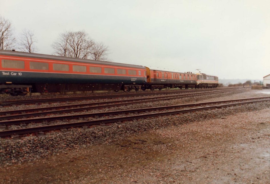
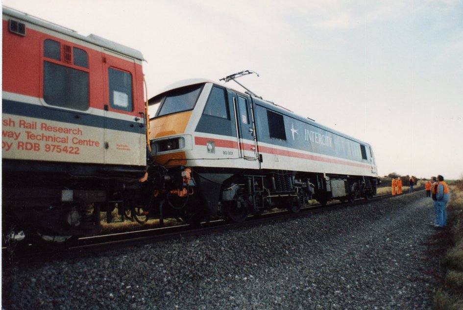
At Old Dalby the aerodynamic tests were carried out by propelling the electric locomotive and test car with a diesel locomotive at speeds up to 100 mile/h. Propelling meant that no other influences affected the
aerodynamic performance of the pantograph. Even having a diesel locomotive in
front of the electric loco could affect the air flow over the roof and hence the
pantograph performance. The BR/BW pantograph could be fine-tuned by adjusting the angle of the aerofoils or in extreme cases by replacing the carbon carriers by a more sympathetic
cross-section profile shape suited to the particular locomotive.
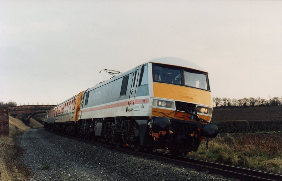
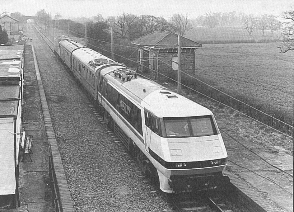
These test were only conducted over the section of the line where the 'dead'
overhead equipment was situated. hence the train would set off from the Control
centre with the pan down and when was under the wires the pan would be raised.
Following the test run of around two miles, the pan would be lowered before
Stanton Tunnel. Failure to do this would most likely have resulted in the pan
striking the tunnel roof.
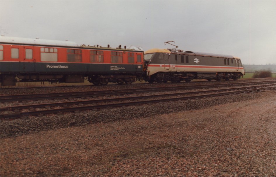
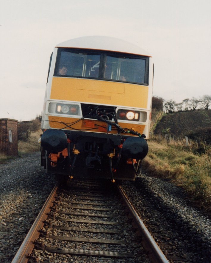
Here are a few photos of the class 89 and class 90 locos undergoing pantograph aerodynamic tuning.
91001 underwent similar tests in 1988.
Click on the picture for a bigger image all
photos courtesy Derek Young except where indicated.